The dampers of this particular design are not suitable for installation in air ducts and ducts of premises with rated explosion and fire safety category A and B and in flammable and explosive mixture intakes.
The KP-1 fire-resisting duct dampers are capable of resisting fire for at least 60 minutes (EI 60) at the temperature of 600 °C.
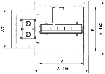
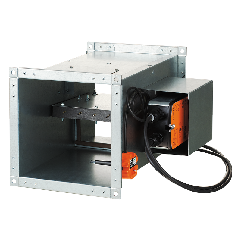
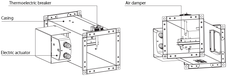
The KP-1 series dampers are made in the general-purpose industrial version with a minimized variety of hardware components using low-alloy galvanized steel. The damper flap is made of fire-resistant material. The duct installation design results in two mounting flanges on the casing for integration into a ventilation ducts (air ducting) and external configuration of the drive mechanism for easier maintenance. The KP-1 series dampers are characterised by a simplified design and the absence of a hot and cold zone baffle. The KP-1 series dampers are equipped with an electric actuator with a built-in return spring and a back-up thermal breaker.
Setting the damper to operating position (direct fire contact): remotely, via electric actuator. The damper can be set to the operating or protective position either remotely via the control panel or manually using the manual cocking handle which is always included in the standard delivery set of the electric actuator.
In case of the remote control panel failure, the backup thermal breaker interrupts the power supply to the electric actuator and the return spring sets the damper to the operating position. Emergency damper actuation: the damper flap is set to the protective position automatically (damper unaffected by fire).
The electric actuator remains energized at all times.
In case of an emergency actuation (direct fire contact): the electric actuator equipped with a return spring is de-energized and the damper flap is set to the operating position by means of the spring energy. In case of a power failure not related to fire and its subsequent restoration at the actuator with a return spring, the damper flap returns to protective position.
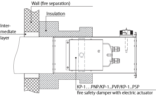
The damper must be installed into the building envelope structure in accordance with the applicable standards and regulations. The seal fire resistance must be at least equal to that of the building envelope.
The dampers can be installed in any position in vertical and horizontal ducts of fire-protection structures.
The ducts for damper installation must be made in such a way so as to prevent the transfer of loads caused by the fire-protection structures to the damper casing.
The adjoining air duct must be suspended in such a way so as to prevent the transfer of air duct load to the damper flange.
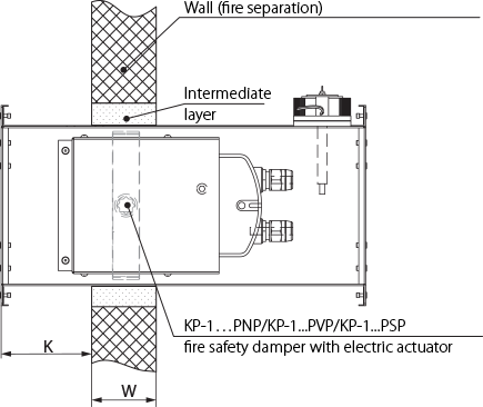
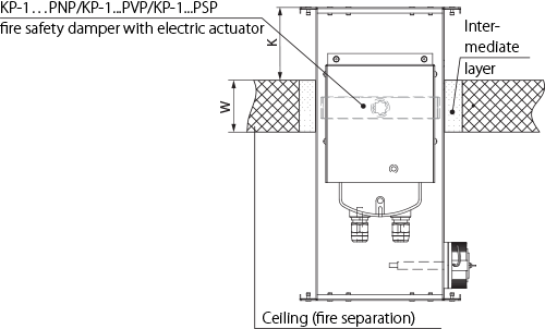
The minimum free space for accessing the control parts must be at least 350 mm. Make sure to arrange an inspection hole. While carrying out the installation consider size K. When two or more dampers are installed into the same fire-protection separation structure, the distance between the two adjacent dampers must be at least 200 mm.
The damper must be installed in such a way so that the damper flap (in its closed position) is located in the fire-protection separation structure. If such installation is not possible, the damper casing part between the fire-protection separation structure and the damper flap must be insulated with a suitable material pursuant to the applicable standards. The damper control mechanism must be protected against damage and contamination. The damper casing must not deform any deformation during embedding. After the installation the flap must not catch against the damper casing while opening or closing. The fire safety damper can be integrated into a tight wall structure – e.g. made of conventional concrete work of minimum width W = 100 mm or into a plasterboard wall of the necessary fire resistance class or into a tight ceiling structure – e.g. made of conventional concrete of minimum width W = 150 mm. Do not use any foaming substances for sealing the damper in the separation structure.