The fire dampers are intended for automatic closing of process openings and air duct penetrations in intermediate floors, walls and partitions, as well as closing of openings in supply and exhaust ducts of smoke ventilation systems.
The dampers of this particular design are not suitable for installation in air ducts and ducts of premises with rated explosion and fire safety category A and B and in flammable and explosive mixture intakes. The KP-2...72S fire-resisting duct dampers are capable of resisting fire for at least 120 minutes (EI 120) at the temperature of 600 °C.
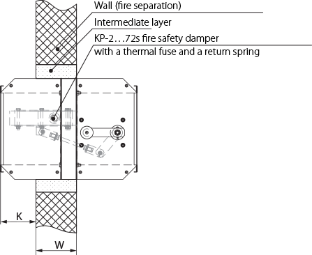
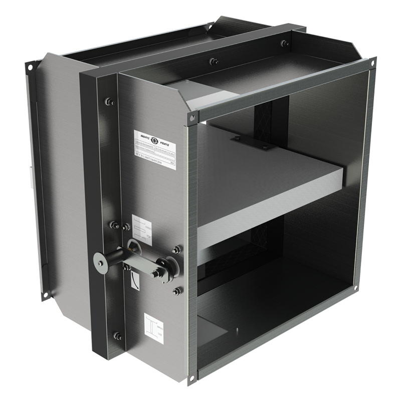
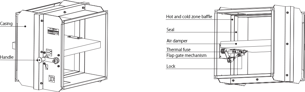
The KP-2...72S series dampers are made in the general-purpose industrial version with a minimized variety of hardware components using low-alloy galvanized steel. The damper flap is made of fire-resistant material. The duct installation design results in two mounting flanges on the casing for integration into a ventilation ducts (air ducting) and external configuration of the drive mechanism for easier maintenance. The KP-2...72S series dampers are equipped with mechanical actuating unit with a thermal fuse and a return spring. The damper is set to the operating position upon the thermal fuse breakdown resulting from a temperature increase. The damper can then be re-set to the protective position only manually by using a handle and by replacing the thermal fuse through the access hole.
Emergency damper actuation: the flap remains in protective position (damper unaffected by fire) and is fixed by a thermal fuse (when the flap is installed in security position, a reverse spring is activated).
Upon emergency actuation (damper directly affected by fire) the thermal fuse breaks down and the return spring moves the flap to operating position.
Upon an emergency activation (direct damper contact with fire) the thermal fuse breaks down enabling the lock with releases the handle allowing the return spring to set the damper flap to the operating position.
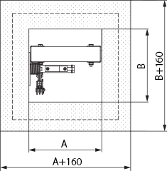
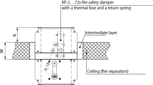
The damper must be installed into the building envelope structure in accordance with the applicable standards and regulations. The seal fire resistance must be at least equal to that of the building envelope. The dampers can be installed in any position in vertical and horizontal ducts of fire-protection structures. The ducts for damper installation must be made in such a way so as to prevent the transfer of loads caused by the fire-protection structures to the damper casing. The adjoining air duct must be suspended in such a way so as to prevent the transfer of air duct load to the damper flange. The minimum free space for accessing the control parts must be at least 350 mm. Make sure to arrange an inspection hole. While carrying out the installation consider size K. When two or more dampers are installed into the same fire-protection separation structure, the distance between the two adjacent dampers must be at least 200 mm. If such installation is not possible, the damper casing part between the fire-protection separation space and the damper flap must be insulated with a suitable material pursuant to the applicable standards.
If such installation is not possible, the damper casing part between the fire-protection separation structure and the damper flap must be insulated with a suitable material pursuant to the applicable standards.
The damper control mechanism must be protected against damage and contamination.
The damper casing must not deform any deformation during embedding. After the installation the flap must not catch against the damper casing while opening or closing.
The fire safety damper can be integrated into a tight wall structure - e.g. made of conventional concrete work of minimum width W = 100 mm or into a plasterboard wall of the necessary fire resistance class or into a tight ceiling structure - e.g. made of conventional concrete of minimum width W = 150 mm. Do not use any foaming substances for sealing the damper in the separation structure.