Products
Domestic ventilation
Residential axial fans
Design Concept System
Domestic centrifugal fans
Ceiling Exhaust Fans
Air inlets
Electrical accessories
Commercial and industrial ventilation
Inline fans
Roof fans
Kitchen fans
Axial fans
Chimney fans
Radial fans
Supply ventilation units
Air heating systems
Accessories for ventilating systems
Electrical accessories
X-Vent system
Decentralized ventilation units
Decentralized HRU for residential buildings
Decentralized HRU for residential and commercial buildings
Decentralized HRU for schools and public buildings
Controls
Centralized air handling units
Counterflow residential AHU
Rotary residential AHU
Crossflow residential AHU
Counterflow commercial AHU
Rotary commercial AHU
Crossflow commercial AHU
Bespoke units
Accessories for ventilation systems
Electrical accessories
Smoke extraction
Axial smoke extraction fans
Сentrifugal smoke extraction fans
Jet fans
Fire dampers
Fire accessories
Frequency converters
Air distribution
Radial ductwork
Plastic ductwork
Metal ductwork
Flexible ducts
Grilles
Diffusers and valves
Access doors
Fittings
HVAC grilles
Downloads
Downloads
Certificates
Catalogs
BIM/CAD models
Equipment selection
Contact us
Contacts
Support
About us
About us
Sustainable development
Production
References
News
EN
UA
DE
RU
About us
News
References
Old version of the site
/
Product catalogue
/
Smoke extraction
/
Fire dampers
/
Smoke dampers
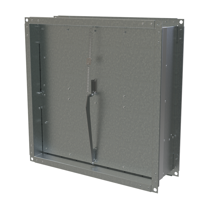
/ KRDP
Series Vents KRDP
Excess pressure valves are used to regulate pressure difference in fire protection ventilation systems
Model range
Downloads
Lineup Vents KRDP
Download PDF
Datasheet
"KRDP" product description 03-2023
374 Kb
Manual
"KRDP" user's manual 09-2023 (V243-1EN-01)
1.03 Mb
Image
KRDP - image 1
529 Kb